Reverse engineering the Motorola Sensorhub
Part 2: TODO?
For the impatient: jump straight to the juicy firmware bits. Accompanying repo at https://github.com/Ristovski/motosh-fw/.
Introduction
Almost all Motorola smartphones come with a nifty feature called "Moto Actions" or "Moto Gestures", which - taken straight from Motorola - "allow you to perform specific gestures to perform certain tasks".
Some examples of these actions are:
- Twist your wrist twice quickly to open the camera from any screen.
- Make a chopping motion to turn the flashlight on or off. (this one is very useful)
Clearly, this is something that would require constant processing of the phones sensors, and judging by the good battery life - it's unlikely to be done on the phones processor itself.
Further digging
Doing some basic Googling we stumble upon the following application published by Motorola - Motorola Sensor Services.
Looking at the description we find the following clue: "Motorola Sensor Services allows you to keep your Sensor firmware updated to allow for the best phone experience."
This makes it clear it is either utilizing the Qualcomm Hexagon DSP (Digital Signal Processor) present on Qualcomm SoCs or a custom DSP to process the sensor data.
Of course, a keen eye would notice the stm401 in the package name (com.motorola.sensorhub.stm401.updater) - which is a STM32F4 Series MCU.
Notice: Rest of article based on Motorola Moto G5 Plus, although should be accurate for other Moto models too.
Finding the exact MCU
Sparing you some boring investigative work, one can find two drivers in the kernel sources, one being stml00x and the other moto-sensorhub.
Functionally they seem identical - it is likely one is simply a newer generation. This can be confirmed by checking the default kernel config on the phone:
/ # zcat /proc/config.gz | grep -E "STML0|MOTOSH"
# CONFIG_SENSORS_MOTOSH is not set
CONFIG_SENSORS_STML0XX=y
Sadly, this still doesn't answer what the exact MCU model is on our device of choice, but luckily for us leaked schematics are easy to find.
TODO: Our own reverse-engineered schematic to keep Motorola lawyers happy. For now, imagine a schematic with a nice-looking part number that reads STM32L051T8Y6D.
Firmware
Now that we have identified the exact MCU (STM32L051T8), we can start poking around the firmware.
The sensorhub firmware binary resides under /etc/firmware/sensorhubfw.bin, let's take a closer look at it.
/tmp/fw $ file sensorhubfw.bin
sensorhubfw.bin: DOS executable (COM, 0x8C-variant)
/tmp/fw $ xxd sensorhubfw.bin | head -n 10
00000000: 8c1e 0020 4502 0008 c100 0008 c500 0008  ... E...........
00000010: c900 0008 cd00 0008 d100 0008 0000 0000  ................
00000020: 0000 0000 0000 0000 0000 0000 19b2 0008  ................
00000030: d900 0008 0000 0000 19b2 0008 e100 0008  ................
00000040: 7f01 0008 7f01 0008 f300 0008 7f01 0008  ................
00000050: 7f01 0008 0501 0008 1701 0008 2901 0008  ............)...
00000060: 7f01 0008 7f01 0008 3b01 0008 7f01 0008  ........;.......
00000070: 4d01 0008 5f01 0008 7f01 0008 7f01 0008  M..._...........
00000080: 7f01 0008 7f01 0008 7f01 0008 7f01 0008  ................
00000090: 7f01 0008 7f01 0008 7f01 0008 7f01 0008  ................
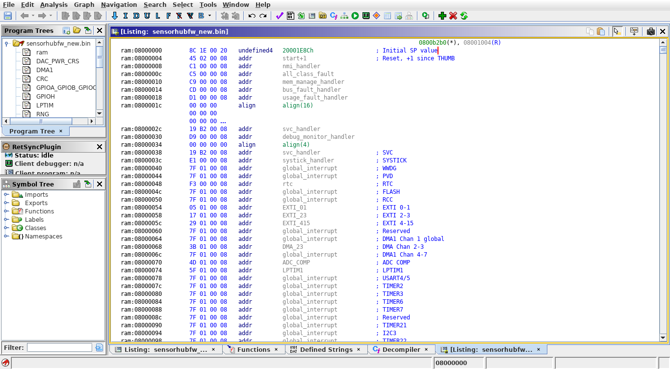
Experienced readers will notice this is the reset vector table
/tmp/fw $ strings sensorhubfw.bin
[OMITTED FOR LENGTH]
Boot Complete %d
Acc Fact: %d, %d, %d, NV: %d
Invalid BMI160 irq
BMI160 read fail
Algo engine timeout
AKM read fail %d
prox calibration complete: %d
prox start calibration: noise drop
prox start cali:prox off
Health id %d, H %d  F %d
[OMITTED FOR LENGTH]
AKM09912 I2C read failure
AKM09912 I2C write failure
[OMITTED FOR LENGTH]
Panic!
## M0 Fault Info ##
Fault Type: %s
[OMITTED FOR LENGTH]
0800d7ac
strings gave us a lot of info about the firmware itself:
- The firmware is not encrypted, as can be seen by the structure of the output and presence of strings
- The exact sensors being used are:
- The MCU itself a Cortex-M0 core (which we already knew from the MCUs datasheet)
- Location of the version string but why?:
hudsoncm-NoUpstream-NPP25.137-58-0-g1e701b5-2016-12-22T17:07:56+00:00
The next logical step would be loading the firmware in your favorite reverse engineering suite, like Ghidra.
Inspecting the firmware
Before we load the firmware, we can utilize a trick to not only save us time but also save us some pain and misery. And that's to convert the raw binary file to an ELF, with the use of objcopy.
Since we know the FLASH memory address of the STM32 (0x08000000), we can run the following:
/tmp/fw $ arm-none-eabi-objcopy -I binary -O elf32-little \
--change-section-address .data=0x08000000 sensorhubfw.bin sensorhub.elf
Now we can load the .elf in Ghidra:
Ghidra fails to detect the architecture for some reason, so we need to set it manually. Which in this case is 

ARM Cortex 32-bit Little Endian
Also make sure to select "Decompiler Parameter ID" in the Analyzers window that pops up, which will improve the analysis/decompilation.
You can also run SVD Loader, which is a Ghidra plugin that auto-generates sections for peripherals read from SVD files. This makes it easy to see what peripherals a certain function is touching, which can oftentimes be enough to see if a function is interesting to us or not.
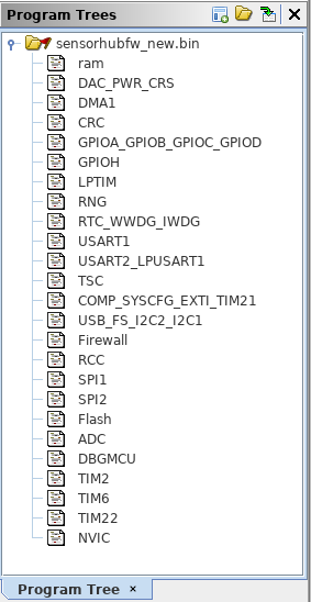
SVD-Loader automatically creates sections for each peripheral.
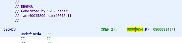
Listing cross-references to the DBGMCU register.
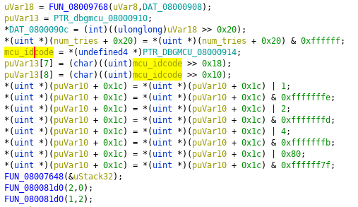
Double clicking on the cross-reference takes us to the function that does some bit-operations on the value from DBGMCU.
A different approach
Even though I spent hours in Ghidra, to the point where out of frustration I had the whole vector table mapped out:
Misery and pain.
going over the disassembly/decompilation was still a pain, especially without being able to look at what it's doing in real time.
Then I thought - wouldn't it be nice if we could debug the firmware at runtime?
At a first glance, qemu_stm32 seems like a prime condidate for being able to emulate the firmware. Should be fairly easy, right? All we would have to do is define a QEMU machine for our STM32 MCU, then define all the peripherals - which would take hours of reading the specs/docs - then have no idea if it's actually working correctly, cue countless recompiles... you get the idea.
A far more sane solution would be using Renode, which is probably the most useful and undocumented, not to mention straight-up unknown piece of software for stuff like this, ever.
What is Renode? Taken from it's website: "Renode is an open source software development framework with commercial support from Antmicro that lets you develop, debug and test multi-node device systems reliably, scalably and effectively."
Which doesn't sound like much until you realize it's basically like QEMU, only better and also on steroids.
Renode allows you to define a "platform" which is a collection of devices - like CPUs, memory, sensors, whole boards etc, and run firmware on them. It comes with a modest collection of pre-made boards like the STM32F4-based "Discovery" or the Xilinx Zynq-based "ZedBoard".
The main point of Renode is being able to extend/modify the existing definitions - perfect for our use case.
Creating a Renode model
To spare our sanity, we will re-use the SVD we loaded in Ghidra in order to extract all the peripheral addresses/interrupts etc.
I have written a hacky script which produces nice human-readable output given a SVD file:
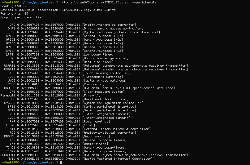
Listing peripherals.
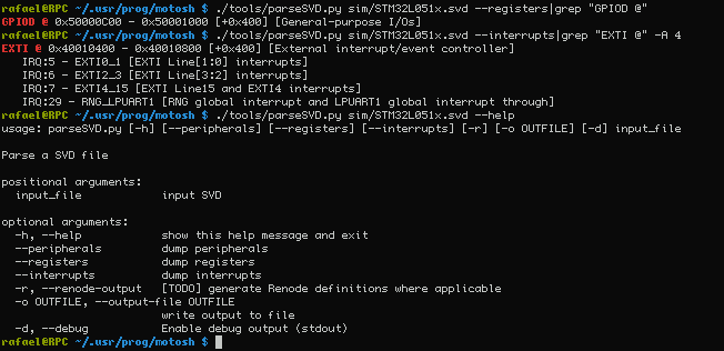
Very useful for finding registers/interrupts.
Renodes platform description format looks like this:
flash: Memory.MappedMemory @ sysbus 0x08000000
    size: 0x10000

systemMemory: Memory.MappedMemory @ sysbus 0x1FF00000
    size: 0x10000

nvic: IRQControllers.NVIC @ sysbus 0xE000E000
    priorityMask: 0xFF
    systickFrequency: 72000000
    IRQ -> cpu@0

cpu: CPU.CortexM @ sysbus
    cpuType: "cortex-m0"
    nvic: nvic
# ...
RCC_CR: Python.PythonPeripheral @ sysbus 0x40021000
    size: 0x4
    initable: true
    script: "request.value = 0x8a1"
Constructing a description of the sensorhub is pretty straight-forward apart from the following gotchas:
- Renodes NVIC needs to be loaded at
0xE000E000instead of0xE000E100because it also handles theSysTickSystem Timer which is at0xE000E010. - Other misc stuff like RCC requiring some initial values.
Using Renode is a bit finicky so I have written a series of helper scripts/files which you can find under the sim directory.
Simulating the firmware in Renode.
Epilogue
Right now, we can boot the official firmware in Renode, which then appears to try and communicate with the sensors. We can also load our own "testing" firmware, which right now is enough to at least test the accuracy of Renode.
Oh, did I mention you can debug all this with gdb under Renode too?
In Part 2 we might try and get gdb interoperability working, and implement basic functionality of the sensors.